DISCLAIMER : THE AUTHOR OF THIS PAGE CANNOT BE HELD RESPONSIBLE IN ANY WAY FOR INJURIES FOLLOWING THE USE OF LASER LIGHT, NOR FOLLOWING THE TECHNIQUES DISCRIBED BELOW. also, optical testing results are not garanteed by the author,
Optical testing was always a very chalenging job. Several methods are widely spread and understood n the mirror making community.
Foucault, Ronchi, Caustic are some fine tests that can reveal almost all the information needed to correct and finalise the pollishing of an optical component.
Nontheless, all these tests give you only an impression of the quality of the optics. Not a quantification of the errors.
For this, there is needed an interferometric test. This test is quantifying the errors, easy to record on photograph, easy to understand were corrections on the optics are needed.
There are only tree negative points:
1. You cannot find very much information about these kind of tests.
2. It is not an easy job to hold two beams of light constantly without vibrations against each other within a fraction of a wavelenght.
3. These tests are best done with monochramatic laserlight. BE CAREFULL with these lightsources. Laserlight can damage your eyes very quickly.
For my interferometric tester i had some criteria in mind:
1. Easy setup for quick measuring of different type of surfaces.
2. As steady as possible to avoid lose of interferometric pattern.
3. Transportable to take measures on complete optical trains on other telescopes.
4. easy to adjust and to understand to allow other people to measure their own optics.
5. made out of easy to find optical components, not the very critical reference elements that you can buy at great cost.
The first type of interferometer build was of the "Bath"-type.
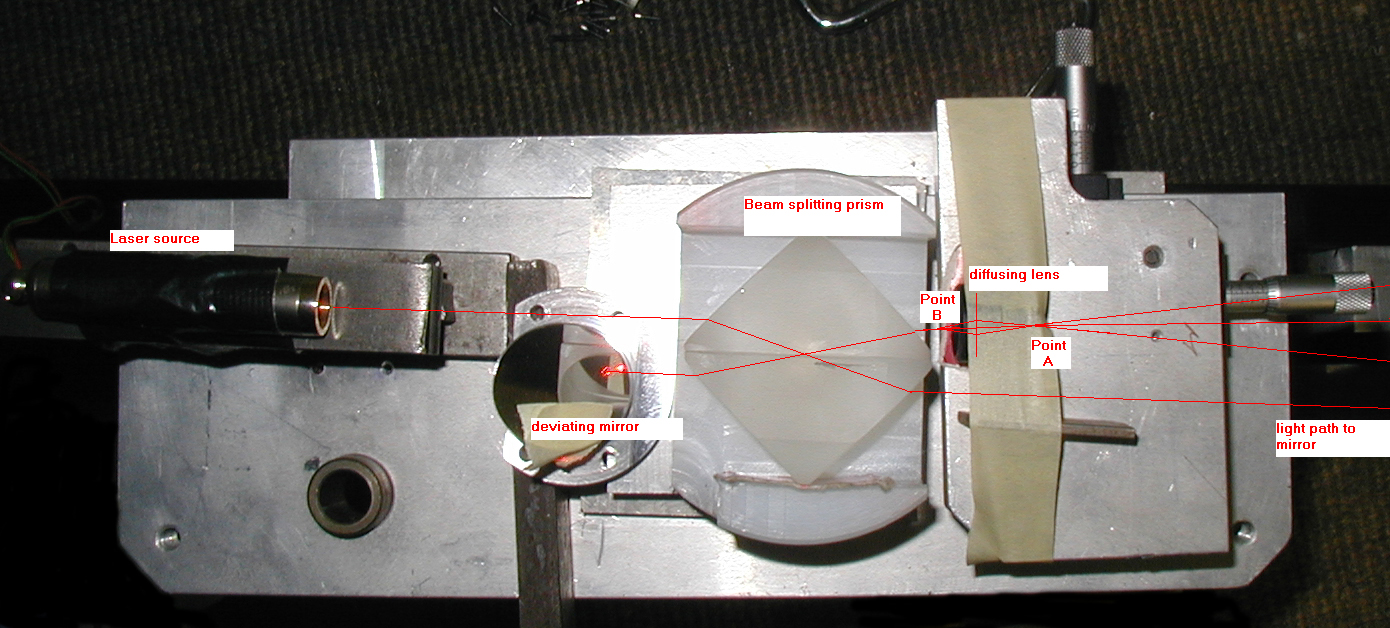
Here is the path layout of my home build common path "bath"- interferometer.(click on the image for larger scale)
All of these criteria were found in the following setup (see picture above).
This is a common path interferometer. errors in the optical components are cancelled out becaus the two light beams are traveling trough the same components.
The lightpath is the following.
The laser sorts a beam to the beamsplitter. This splitter is made out of two prisms (recovered from a large binocular). to give these prisms good surface contact, just humidify them by breathing on them and then putting them together by sliding them from the edge to the middle over each other. This splitter makes two wavefronts of the same intensity. You can change the intensity between both outcoming rays by adjusting the prisms. Try to find prisms that are at least 25 mm (1inch) long on their smallest surface and try to find some that have polished surfaces right to the edge (or just 2mm from the edge, grounded rough). Once adjusted to have two beams spaced 1cm apart (in front of the prisms) direct the whole optical setup towards the mirror under test. adjust the tilt of the prisms so that both beams are falling together on the same spot somewhere in the middle of the tested component) adjust already the distace between mirror and setup so that the point 5 mm in front of the prisms is at the same distance from the mirror as two times the focal lenght (parabolic) or one time the focal lenght for a spherical surface. Now find a little lens that has a biconvex surface about 5 or 10 mm in diameter and place this in front of the prisms (10 mm) in one of the beams. The focal lenght of this lens must be as short as you can find in order to iluminate the whole surface of the optical component under test. Try to have only optical components that are perfectly clean otherwise, they will have lots of diffraction points due to monochromatic laser light. BE CAREFULL again with reflected laser beams, NEVER look directly into the beams. Even indirect beams can damage your eyes. the only difficulty in obtaining interference fringes is to adjust your setup and the mirror inder test so that both reflected points will fall exactly on the original point on the prisms. You must understand the following principle:
Interference can only be obtained when two beams are traveling the same direction and are falling together. The interference is obtaind by the following path. The first beam is leaving the prism and reflected off the mirror under test towards the setup again. It passes trough the biconvex lens and is travelling into the prism again. Because it is only a very little spot of light, it is ignoring the deformation of the mirror. just see this mirror as a perfect plane mirror. Nevertheless, it takes into account the error or even maladjusting of the biconvex lens. The second beam is passing trough the biconvex lens (be aware to have at least the focal lenght of this biconvex lens between the lens and the prism). and it is diverging towards the mirror, illuminating the whole surface. Reflecting back, it accumulates the errors in the surface under test and converge again to the prism, forming a focal point just in front of the prism. You can check this with a piece of paper. Now adjust the tip-tilt of the mirror to ensure bothe reflected spots are falling exactly on the beams leaving the prism. Now you should adjust the distance between the setup and the mirror to ensure the reflected focal spot is at the same distance in front of the prism as the focal spot of the biconvex lens on the prism side. When viewinf the projected light leavinf the prism cube (on the other half of the entering laser beam), you would see the whole mirror under test illuminated with interference frinjes. AGAIN: do not look directly into the beams. adjust all distances to have stable frinjes. In the beginning, do not be frustrated if you see nothing, alignement is that crucial that the smallest error will result in nothing but a illuminated circle without frinjes.
Another type of interferometer was build with the optical components of the ACG (Astronomical contact group) of Ieper Belgium.
This interferometer is of the priniples of Peter Ceravolo. Ceravolo sold the optical components to ACG a few years ago and now, there were put together to produce a second interferometer.
you can find some pictures below.
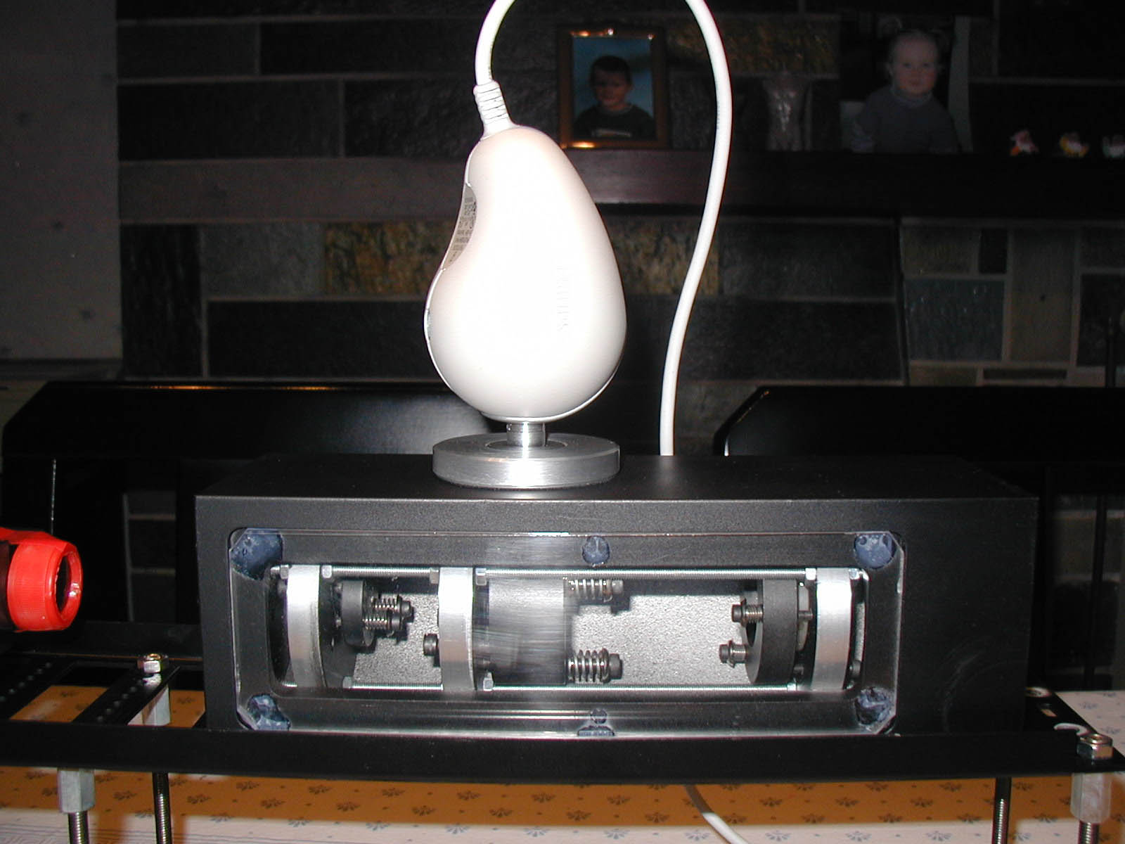
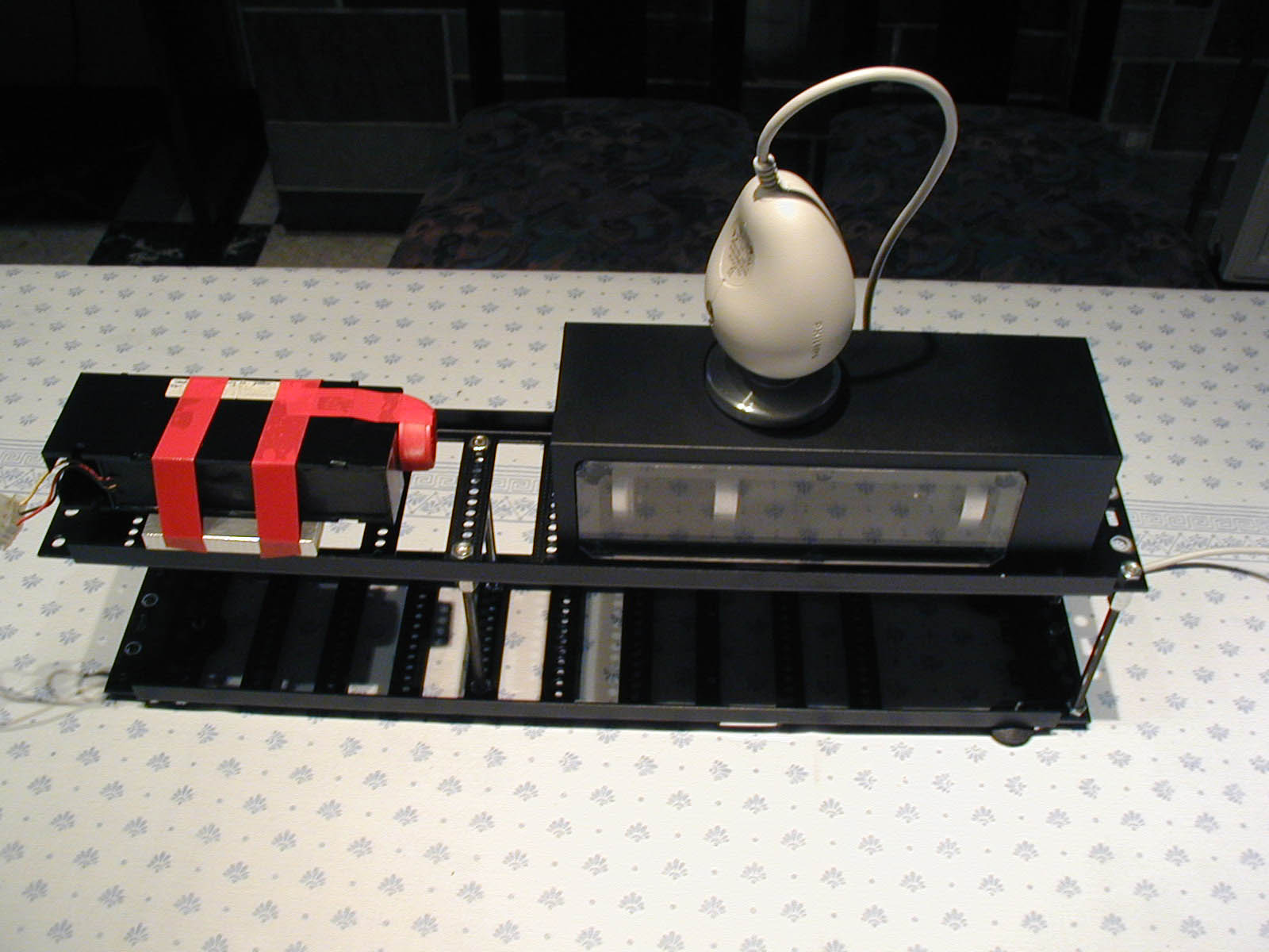
This interferometer has some advantages (and some disadvantages of course). Biggest point is that all optical components are aligned on the same optical axis, so no aberations are introduced. Disadvantage is that you need some optical components that are rather expensive. above you can see the interferometer (inside the cube) containing three optical parts. 1. The grin lens for diverging the beam of laserlight (laser is taped to the construction with red electrical tape) 2.the beamsplitter to redirect the laserlight out of the instrument 3.the reference element to create the reference wavefront.
Other components are the mirror under test (not shown), the laser, a 5 mW red laser, and the webcam to make the laserpattern visible on a safe manner.
The grin lens is diverging the beam, passing through the beamsplitter and refelecting off the reference element thus creating a reference wavefront that is coming to focus above the instrument deviated by the beamsplitter. (a second focus can be found back at the laser pinhole, see picture below). The other (non reflected) part of light is passing through the reference element and is falling on the optical component under test. This is refelected back to the instrument and is combined with the first wavefront thus forming an interferometric pattern.
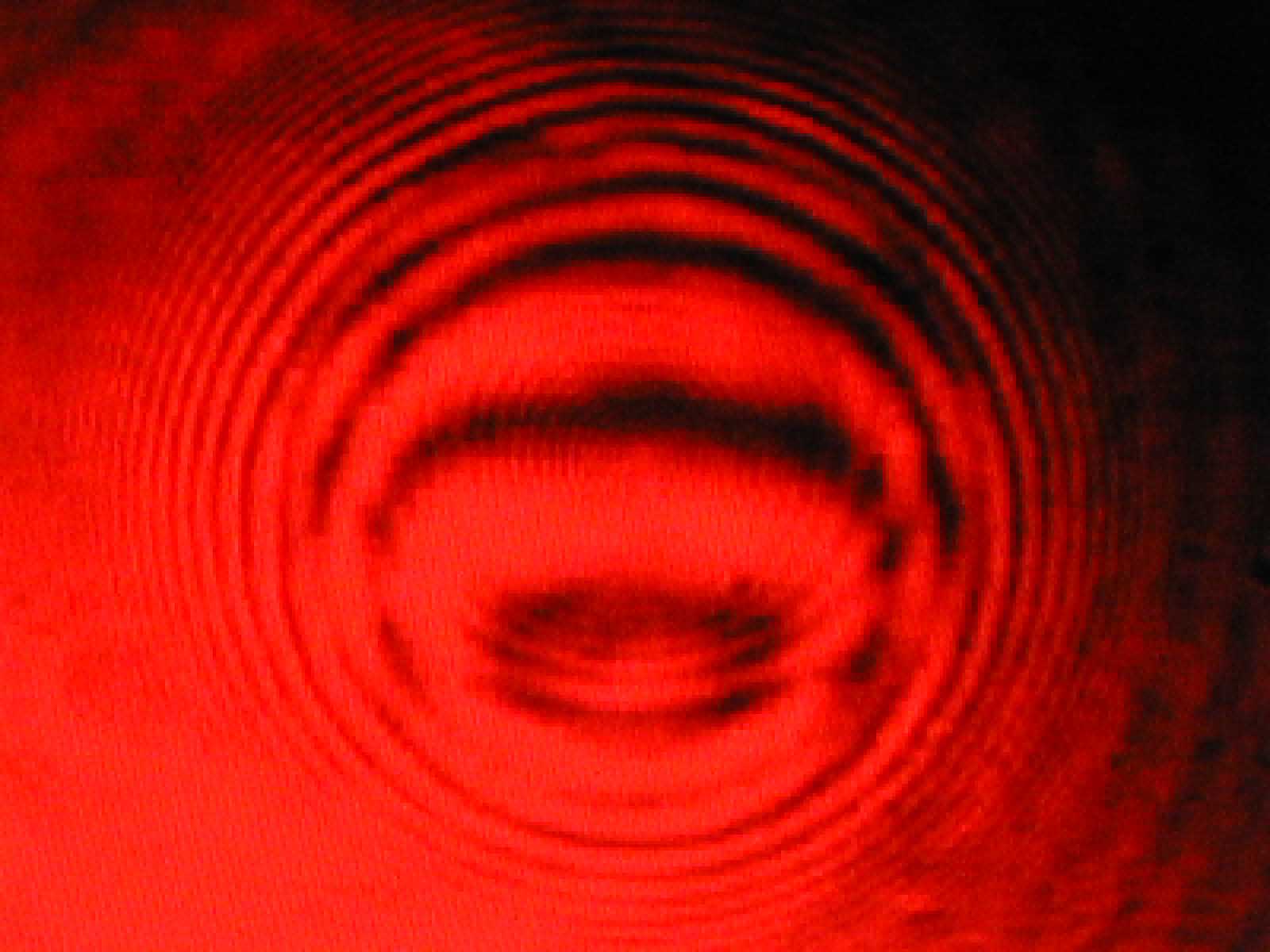
Some of the preliminary results are the pictures underneath:
 a simple
lens
a simple
lens
 a 30
cm mirror who is supposed to be spherical.
a 30
cm mirror who is supposed to be spherical.
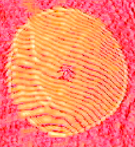
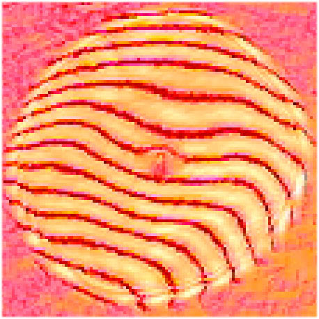
The most interesting fact is to examin images from both the BATH interferometer and the CERAVOLO interferometer
Aberations in both images arerather similar, left is the ceravolo-interferogram and right is the bath-interferogram of the same mirror, a 30 cm sphere(well, almost a sphere....)
Note that these images suffered largely of disturbing air currents flowing through the place at the time of making the images..

of coarse their is still very much room for improvement. Underneath there is one of the latest images which is already much more stable and have better contrast.(less air disturbance)
.
As this is a very fast evolving project, some more results will be post in the comming weeks and months.
for the interpretion of the results, i would like to refer to my friends website with first preliminary results of the initial test with these fine instruments:
http://www.digilife.be/club/johan.vanbeselaere/atm/optics/testing/interferometry/lensinte.htm
![]() Sorry, only available in english
Sorry, only available in english
last update: January 23, 2022